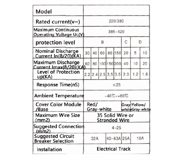
Main Technical Specifications are shown in Table 1 (for example)
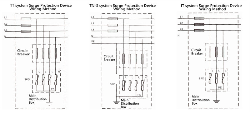
Wiring Diagram
 Main Structure and Working Principle
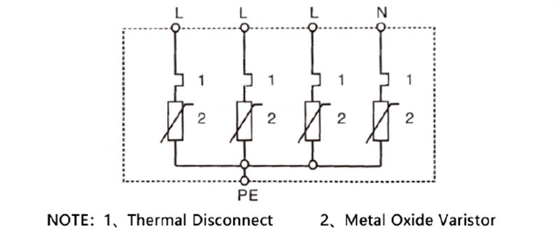
In a three-phase four-wire system, three phase lines and one neutral line are all equipped with protectors connected to the ground. Under normal conditions, the protectors are in a high-resistance state. When the power grid experiences surge overvoltages due to lightning strikes or other reasons, the protectors will rapidly conduict within nanoseconds, diverting the surge overvoltage into the earth, thereby protecting the electrical equipment on the grid. Once the surge Voltage passes through the protector and disappears, the protector returns to a high-resistance state, thus not affecting the normal operation of the power grid. The electrical schematic of the surge protector is shown in the figure below.
Installation Methods and Precautions
(1). The connecting wires should be of the same capacity as or greater than the power supply lines, and the total length should be controlled within 0.5 meters, with shorter lengths being preferable.
(2). A corresponding Circuit Breaker or fuse must be connected in series at the front end of the surge protector.
(3). Power must be disconnected during installation.
(4). Surge Protector Troubleshooting
①The indicator window of the module is green (normal); when the module deteriorates, the indicator window turns red and must be replaced promptly.
②Surge protectors can be equipped with (FS) remote telesignal alarm
systems. The telesignal contact points consist of one normally open and one normally closed contact. If a module or multiple modules of the surge protector fail, the contact points will close, triggering a fault alarm signal, indicating that the module has malfunctioned and needs to be replaced.
③Regularly inspect the circuit breakers or fuses connected in series with the line.
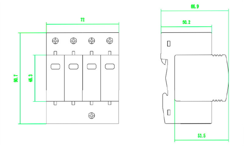
Outer dimensions (length x width x height)
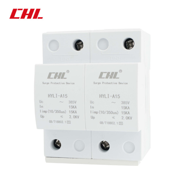
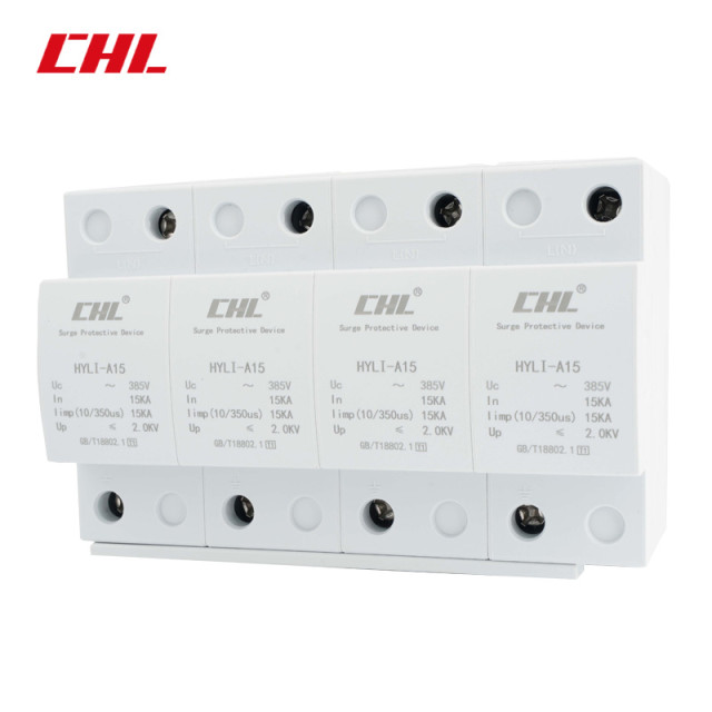
small size mold: 90x72x65.5
medium size mold: 90x108x65.5
large size mold: 90x144x65.5



 Main Structure and Working Principle


